Digital Engineering Fundamentals
Est. read time: 5 minutes | Last updated: July 27, 2026 by John Gentile
Contents
- Overview
- Resets
- Timing
- Designing for Performance
- Designing for Power
- Digital Design Process & Tools
- References
Overview
People who are really serious about software should make their own hardware- Alan Kay
One of the keys to digital design when working with HDL languages is “what will this synthesize to in real hardware?”
In general, digital design can take a lot of cues from SW: code reviews, tooling, algorithms, etc. especially for Continuous Integration (CI) as the same needs as SW are present (automated regression tests, automated builds, hooks with Git repo, etc.); thus, testbenches (unit level or BFM) that are not self-checking are not useful for these CI tests, or even a new reader of the design (e.g. self-documenting code).
Resets
I/O resets are asynchronous (for safety in case no clocks), but everything internal should be synchronous, especially since how FPGAs define FFs now
Timing
- Setup & Hold Times
- Minimize routing and logic delay
- High routing delay is indicative of high design congestion (e.g. an FPGA design > 80% utilization) or high signal fanout
- Fanout is when one registered signal drives some number of “loads” (e.g. receiving registers). The most common high fanout signal is resets which drive many circuits. Pipelining, or adding registers, to these signals can help reduce high fanout; and specifically for resets, only resetting logic that needs to be reset (e.x. some components with buses that have valid/ready handshaking, need only reset those handshake/control signals).
- High logic delay is indicative of many Levels of Logic (LoL)
- Levels of Logic (LoL) is how many gates a signal path must propagate through between register (e.g. flip-flop) stages. The more levels of logic, the longer the logic delay, and the harder it is to meet timing. Similar to above, adding pipelining/registers- or reducing the amount/complexity of combinatorial logic- reduces LoL.
- Note that the true LoL measure comes after Synthesis, as the tool maps combinatorial logic into device specific resources (e.g. LUT, RAM, MUX, etc.). Reading synthesis reports (such as Vivado’s
report_design_analysis) is thus critical to measure LoL, and to see which paths have the highest levels of logic (focus on these paths first if timing not met).
- High routing delay is indicative of high design congestion (e.g. an FPGA design > 80% utilization) or high signal fanout
- Place-and-Route (PaR) tools optimize the hardest (“critical”) paths first. So even highly registered logic in other places in a design can fail (e.g. due to high routing delay) when other paths with high LoL are prioritized first (the synth tool assumes you know what you’re doing, and that high LoL is on purpose).
- Different synthesis & PaR strategies to help
- For very large devices (e.g. Stacked Silicon Interconnect (SSI)), register across Super Logic Regions (SLR) boundaries with custom directives/constraints
Designing for Performance
- Pipeline early & often: in modern digital targets (like FPGAs), flip-flops are likely the cheapest resource in the programmable fabric. Thus while designing, err on the side of more inferred registers; this increases your chances on meeting static timing the first time. Worst case, further optimization can remove unnecessary FFs. Remember that premature optimization is a folly in engineering design.
- When working with large RAM primitives that span multiple blocks (e.x. multiple block RAMs (BRAM) chained together to create large FIFOs/tables), registering between RAM blocks can help meet timing if the read/write latency can tolerate it.
- Based on requirements, HDL designs should maintain a balance between portability (e.g. using vendor/tool agnostic code patterns) and optimizing for device-specific primitives/features (e.g. coding for inference of primitives such as DSP or RAM blocks, to direct vendor component instantiation).
- Sometimes simple coding style changes can have very different synthesis/implementation results, while having exactly the same functionality (e.g. cycle-accurate behavior).
- For example, Vivado synthesis by default uses Slice/CLB logic for addition/subtraction logic. In Xilinx Versal, they changed the carry-chain primitive to a
LOOKAHEAD8type, which by their docs, utilizes more LUTs for accumulators/counters than previous generations. Very wide (e.x. 64bit) binary counters can create timing pressure with high levels of logic due to this long carry chain. However, many FPGA vendor parts have DSP blocks which have hardened arithmetic circuits, and wide, internal accumulators (e.x. the DSP58 block in Xilinx Versal has a 58 bit accumulator which can be cascaded to create much larger arithmetic circuits). By telling Vivado to infer DSP blocks for certain counters (by using synthesis attributes), levels of logic can be significantly reduced. - Looking at synthesis reports/logs can help verify attributes or show potential for device-primitive mapping.
- For example, Vivado synthesis by default uses Slice/CLB logic for addition/subtraction logic. In Xilinx Versal, they changed the carry-chain primitive to a
- Sometimes simple coding style changes can have very different synthesis/implementation results, while having exactly the same functionality (e.g. cycle-accurate behavior).
Skid Buffers
One of the most important building blocks for high-throughput, pipelined, digital designs is the skid buffer (or register slice). When dealing with ready/valid handshaking between stages, you don’t want to naively just register the ready signal when getting backpressure from a downstream stage, as this could bubble up delays in the processing, decreasing overall throughput. Instead, a skid buffer can be seen as a lightweight, 2-deep FIFO that can allow 10% throughput without incurring bubble cycles.
For more information, see:
- AMD-Xilinx AXI Register Slice LogiCORE IP Product Guide (PG373)
- Pipeline Skid Buffer - fpgacpu.ca
- Building a Skid Buffer for AXI processing - zipcpu
- Designing Skid Buffers for Pipelines - Chipmunk Logic
Designing for Power
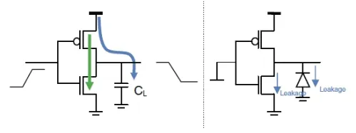
CMOS digital circuits dissipate power in three main ways: dynamic, short circuit, and leakage power. Of note to the digital designer, dynamic power consumption.
References
Digital Design Process & Tools
Design Entry (Front End)
The “front end” of digital systems are designed using Hardware Description Languages like Verilog or VHDL. Though not always resource efficient, there has been many attempts at “High Level Synthesis” (HLS), where digital logic can be designed in a higher-level language, like C++ or Python. Some are vendor specific like AMD-Xilinx HLS, others are open-source projects like:
- JulianKemmerer/PipelineC: A C-like hardware description language (HDL) adding high level synthesis(HLS)-like automatic pipelining as a language construct/compiler feature.
- hls4ml: Python package to create firmware implementations of machine learning algorithms using HLS.
FPGA Prototyping
FPGAs allow for rapid prototyping (and deployment) of digital logic, as the ASIC is already complete and needs only have firmware updates to change behavior. This also means that some parts of the actual “back end” ASIC development process are not necessary (e.g. analog design, PDK, etc.) though timing constraints and other tool-specific workflows are still necessary.
See this page on FPGA tools & design.
Simulation
See this page on verification & testing of HDL/RTL designs.
Documentation/Modeling
- WaveDrom online digital waveform diagraming tool with an easy to use syntax.
References
Maintained by John Gentile • Found a problem on this site? File an Issue
This work is licensed under a Creative Commons Attribution 4.0 International License.![]()