Carrier Recovery & PED/FEDs
Est. read time: 2 minutes | Last updated: July 27, 2026 by John Gentile
Contents
![]()
Frequency Error Detector (FED)
import numpy as np
import matplotlib.pyplot as plt
from scipy import signal

from rfproto import filter, impairments, measurements, multirate, nco, pi_filter, plot, sig_gen
fs = 100.0e3
f_start = -fs/2
f_end = fs/2
num_samples = int(fs) # 1 second
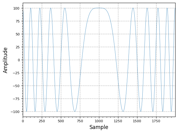
lfm_chirp_sig = sig_gen.cmplx_dt_lfm_chirp(100, f_start, f_end, fs, num_samples)
mid_pt = int(len(lfm_chirp_sig)/2)
margin = 1000
plot.samples(np.real(lfm_chirp_sig[mid_pt - margin:mid_pt + margin]))
plt.show()
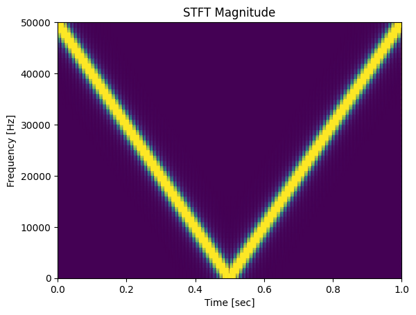
f, t, Zxx = signal.stft(np.real(lfm_chirp_sig), fs, nperseg=100)
plt.pcolormesh(t, f, np.abs(Zxx), vmin=0, vmax=2, shading='gouraud')
plt.title('STFT Magnitude')
plt.ylabel('Frequency [Hz]')
plt.xlabel('Time [sec]')
plt.show()
class Dfd:
    def __init__(self):
       self.z1 = 0 + 1j*0

    def Step(self, x):
        retval = (self.z1.imag * x.real) - (self.z1.real * x.imag)
        self.z1 = x
        return retval
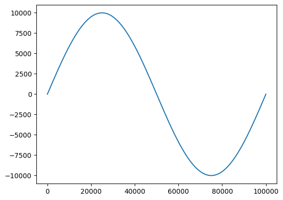
freq_disc = np.zeros(len(lfm_chirp_sig))
test_dfd = Dfd()

for i in range(len(lfm_chirp_sig)):
    freq_disc[i] = test_dfd.Step(lfm_chirp_sig[i])

plt.plot(freq_disc)
plt.show()
Blind, Non-Data Aided (NDA) FLL can be made by RRC/match filtering, Mth power to fold phase into sinusoid which has frequency offset at times the CFO, LPF’ing then using L&R type autocorrelation FED (see above) loop filtered to drive frequency error to zero.
symbol_rate = 5e6
OSR = 4
output_fs = OSR * symbol_rate
rrc_alpha = 0.25
num_symbols = 4096
in_symbols = np.random.randint(0, 4, num_symbols).tolist()
output_iq = sig_gen.gen_mod_signal(
"QPSK",
in_symbols,
output_fs,
symbol_rate,
"RRC",
rrc_alpha,
)
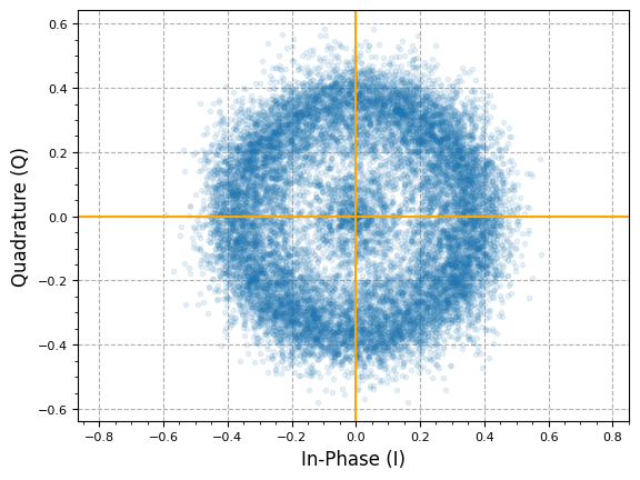
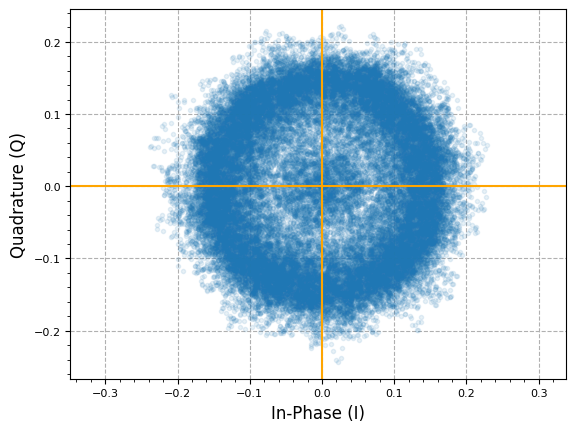
output_iq = impairments.freq_offset_static(output_iq, 1e3, output_fs)
plot.IQ(output_iq, alpha=0.1)
plot.plt.show()
plot.spec_an(output_iq, fs=output_fs, fft_shift=True, show_SFDR=False, y_unit="dB")
plt.show()

M-th Power Detector
Raising an -PSK signal to the -th power is useful in coarse frequency/phase estimation as it wipes phase-modulation, revealing a tone at times the estimated frequency offset.
For example in QPSK, symbols have phases separated by 90° (e.g., 45°, 135°, 225°, 315°), representing 2 bits per symbol. When you raise a complex QPSK symbol to the 4th power, its phase angle is multiplied by 4 (e.g., ). Because (a full circle), all four QPSK symbols, regardless of their initial data-driven phase, end up at the same phase location (e.g., all map to or ). What remains after this operation is primarily the unmodulated carrier’s phase drift (frequency offset) and noise, at the frequency offset (e.x. a 1kHz offset would show up as a 4kHz tone).
iq_4th = output_iq ** 4.0

mth_spec = 20.0 * np.log10(np.abs(np.fft.fftshift(np.fft.fft(iq_4th))))
freqBin = np.linspace(-len(mth_spec) // 2, len(mth_spec) // 2, len(mth_spec)) * (output_fs / len(mth_spec))
plt.plot(freqBin, mth_spec, linewidth=0.5)
plt.show()
print(f"Frequency offset (est.): {freqBin[np.argmax(mth_spec)] / 4.0} Hz")
Frequency offset (est.): 1068.4412967824983 Hz
References
Band Edge Frequency Locked Loop (FLL)
Combined Carrier Recovery
When frequency offset is not significant (e.x. majority of signal bandwidth is still within passband of matched filter, and/or when Coarse Frequency Correction (CFC) has already been applied upstream), frequency and phase errors can be jointly compensated in a carrier recovery scheme.
Decision Directed Phase Detector
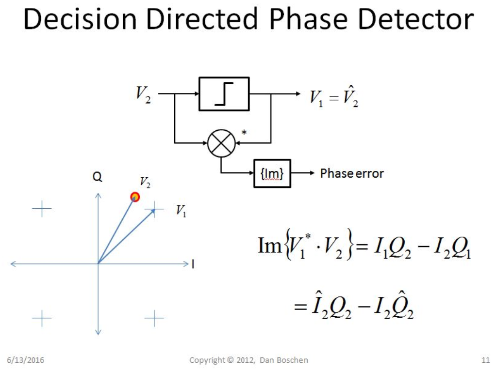
From How to correct the phase offset for QPSK I-Q data
Any M-PSK/QAM modulation can derive a decision-directed phase error via:
NOTE: is the decision point for sample . In QPSK, this is the deviation from the ideal constellation/sampling point (at normalized magnitudes this is ). In general, any M-PSK modulation can derive phase error from subtracting the reference phase/constellation from the input sample (containing phase error).
def qpsk_costas(x, ref_mag):
    # Ideal QPSK I or Q constellation magnitude given input avg. reference magnitude of input samples
    ref_point = ref_mag / np.sqrt(2.0)
    i_decision = np.sign(np.real(x)) * (np.abs(np.real(x)) - ref_point)
    q_decision = np.sign(np.imag(x)) * (np.abs(np.imag(x)) - ref_point)
    return (i_decision * np.imag(x)) - (np.real(x) * q_decision)
M = OSR // 2 # Decimation factor to get to 2x Samples/Symbol (SPS)
rx_rrc = filter.RootRaisedCosine(output_fs, symbol_rate, rrc_alpha, 25)
rx_shaped = signal.lfilter(rx_rrc, 1, output_iq)

downsampled = multirate.decimate(rx_shaped, M)[::2]

plot.IQ(downsampled, alpha=0.1)
plt.show()
cr_nco = nco.Nco(32, 16, 10, output_fs/OSR)
cr_filt = pi_filter.PiFilter(0.001, 1e-1)
N_out = len(downsampled)
nco_out = np.zeros(N_out) + 1j*np.zeros(N_out)
ped_out = np.zeros(N_out)
pi_filt_out = np.zeros(N_out)
for i in range(N_out):
nco_out[i] = downsampled[i] * cr_nco.GetCurrentNcoOutput()
# NOTE: magic number of reference magnitude known a priori from magnitude average calc at bottom of page
ped_out[i] = qpsk_costas(nco_out[i], 11396)
pi_filt_out[i] = cr_filt.Step(ped_out[i])
cr_nco.IncPhaseAcc(pi_filt_out[i])
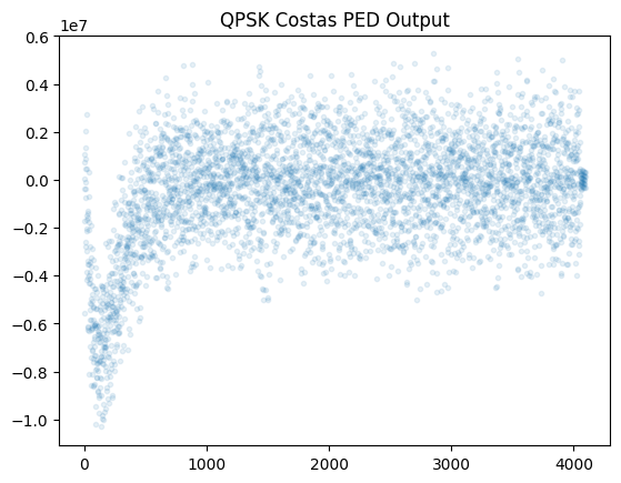
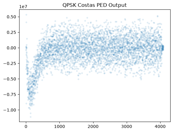
plt.plot(ped_out, '.', alpha=0.1)
plt.title("QPSK Costas PED Output")
plt.show()
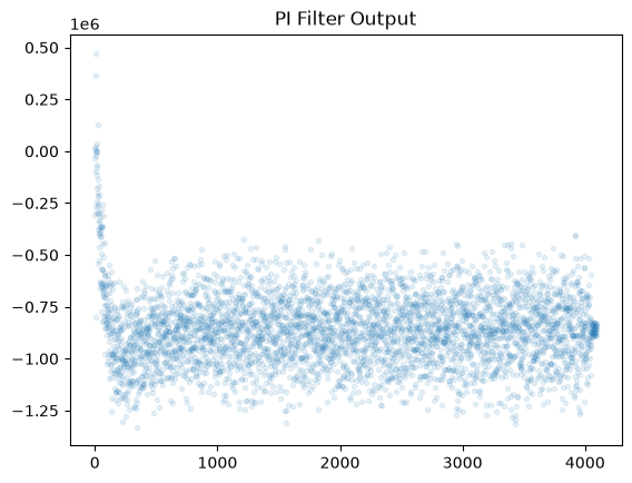
plt.plot(pi_filt_out, '.', alpha=0.1)
plt.title("PI Filter Output")
plt.show()
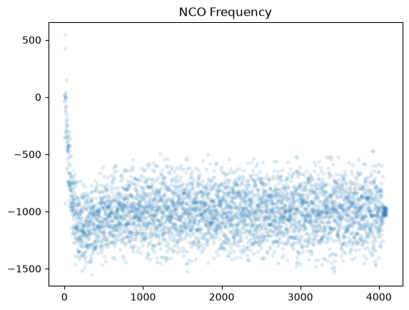
plt.plot(nco.FcwToFreq(pi_filt_out, 32, output_fs/OSR), '.', alpha=0.1)
plt.title("NCO Frequency")
plt.show()
plot.IQ(nco_out, alpha=0.1)
plt.title("I/Q Output")
plt.show()
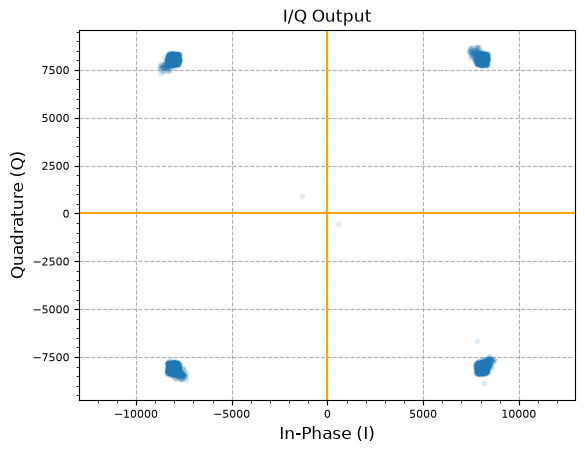
print(f"Output avg. mag: {np.mean(np.abs(nco_out))}")
Output avg. mag: 11387.552066482966
References
- High modulation index PSK - carrier recovery - DSP Stack Exchange
- How to correct the phase offset for QPSK I-Q data - DSP Stack Exchange
- Mathworks Carrier Synchronizer System Object
Maintained by John Gentile • Found a problem on this site? File an Issue
This work is licensed under a Creative Commons Attribution 4.0 International License.![]()