High-Speed Serial
Est. read time: 2 minutes | Last updated: July 27, 2026 by John Gentile
Contents
High-Speed Ethernet L1 & L2 Overview
As a quick refresher, Ethernet (and other high-speed serial protocols) define intermediate layers to their bottom two OSI layers (images of Versal GTM Architecture):
For Ethernet, these sublayers are described as (from lowest to highest layer):
- L1 - Physical Layer (PHY):
- Physical Medium Dependent (PMD) - Sublayer for the physical transceiver in/out of a medium (e.x. optical transceiver to go between electrical lanes & fiber)
- The trailing number in a given Ethernet flavor defines the number of PMD lanes, or commonly, how many fibers or lanes across a medium. For example, in 100GBASE-LR4 there are 4x PMD lanes (each at 25Gb/s NRZ) over the optical transceiver module.
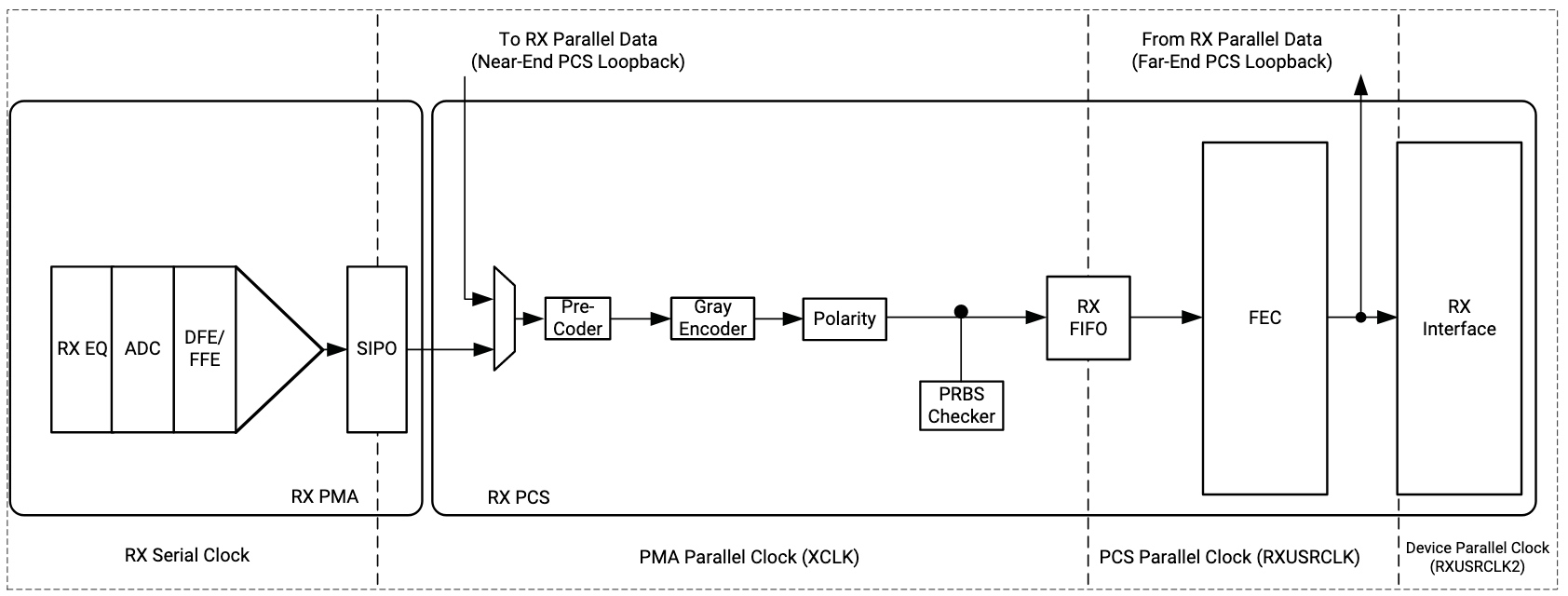
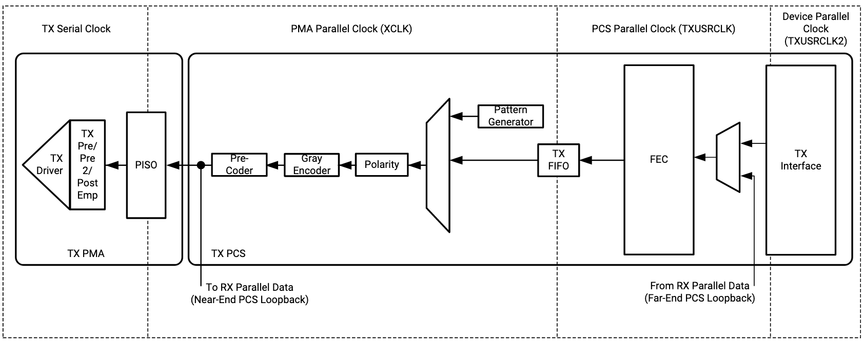
- Physical Medium Attachment (PMA) - mainly the SERDES logic & equalization/pre-emphasis, etc. but also plays a part in how many electrical interface lanes are used by a given standard to interact with the PMD layer. For example, in 100GBASE-DR1, the transceiver module gearboxes 4x 25Gb/s NRZ electrical lanes (PMA) to a single-mode fiber (SMF) 1x 100Gb/s PAM-4 optical signal.
- Physical Coding Sublayer (PCS) - line encoding (64b/66b, 256b/257b), Forward Error Correction (FEC), (de)scrambling, lane alignment, link establishment, etc. but commonly used to describe the channel bonding across PMA lanes to form a synchronous Ethernet Interface
- The starting number in a given Ethernet standard defines the overall data rate of an Ethernet link, to a single MAC/L2 interface. For example, in 100GBASE-LR4, the post-PCS (e.g. w/o line encoding overhead) data rate is 100Gb/s, which is achieved through lane alignment across 4x PMA lanes.
- Physical Medium Dependent (PMD) - Sublayer for the physical transceiver in/out of a medium (e.x. optical transceiver to go between electrical lanes & fiber)
- L2 - Data Link Layer:
- Reconciliation Sublayer (RS) - Handle PHY local/remote fault handshake messaging (PHY link establishment)
- Medium Access Control (MAC)- Sublayer for Ethernet framing and insertion of Frame Check Sequence (FCS, CRC-32 on MAC frame) calculation/checking, Start of Frame Delimiter (SFD) & preamble, Inter-Packet Gap (IPG) padding and enforcement, etc.
- Logical Link Control (LLC) - Interface between MAC & Network layers, commonly EthernetII format
There are several physical signaling standards at the PMD layer with high-speed Ethernet for individual lanes:
- 50G PAM-4: 53.125 GBaud (100Gb/s post-encoding) AN 835: PAM-4 Signaling Fundamentals
- 25G PAM-4: 26.5625 GBaud (50Gb/s post-encoding) PAM-4 Modulation
- 25G NRZ: 26.5625 GBaud (25Gb/s post-encoding) NRZ Modulation
Low Latency Transceiver
In some devices, RX and TX buffers can be bypassed, and a DPLL can be used to lock the receive clock to the transmit clock to remove clock domain crossing (CDC) latency.
Cabling
Everything You Always Wanted to Know About Optical Networking- But Were Afraid to Ask
Eye Diagrams & Measurements
References
- Xilinx In-System IBERT for Eye Analysis (PG246)
- AN687: A Primer on Jitter, Jitter Measurement, and Phase-Locked Loops - SkyWorks
References
- High-Speed Serial I/O Made Simple - AMD-Xilinx Book
- Sam Palermo Courses - Texas A&M
- High Speed Communications - Alphawave Semi YouTube Playlist
- Equalization for High-Speed Serial Interfaces in Xilinx 7 Series FPGA Transceivers (WP419)
- DC Blocking Capacitors
Maintained by John Gentile • Found a problem on this site? File an Issue
This work is licensed under a Creative Commons Attribution 4.0 International License.![]()