TX Pulse Shaping & Matched Filters
Est. read time: 4 minutes | Last updated: July 27, 2026 by John Gentile
Contents

import numpy as np
import matplotlib.pyplot as plt
from scipy import signal
from rfproto import filter, modulation, plot, sig_gen
Matched Filtering
- The why (bandwidth and power amplifiers) -> https://dsp.stackexchange.com/questions/41130/envelope-behavior-difference-between-qpsk-oqpsk-and-pi-4-qpsk
- https://en.wikipedia.org/wiki/Raised-cosine_filter
# CCSDS OQPSK SRRC rolloff=0.5: https://public.ccsds.org/Pubs/413x0g3e1.pdf
rrc_test = filter.RootRaisedCosine(17.225e6, 7.5e6, 0.5, 63)
# The matched filter is a time-reversed and conjugated version of the signal
# NOTE: this is moot for a uniform, real filter...
rrc_mf = np.conj(rrc_test[::-1])
plot.filter_coefficients(rrc_mf)
plt.show()

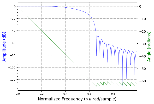
plot.filter_response(rrc_mf)
plt.show()
# simulate random binary input values
num_symbols  = 2400
num_disp_sym = 16
sym_rate     = 1e6 # Baseband symbol rate
# Generate random QPSK symbols
rand_symbols = np.random.randint(0, 4, num_symbols)

L  = 4               # Upsample ratio (Samples per Symbol)
fs = L * sym_rate    # Output sample rate (Hz)

rolloff          = 0.25 # Alpha of RRC
num_filt_symbols = 6    # Symbol length of RRC matched filter

qpsk_tx_filtered = sig_gen.gen_mod_signal(
    "QPSK",
    rand_symbols,
    fs,
    sym_rate,
    "RRC",
    rolloff,
    num_filt_symbols,
)

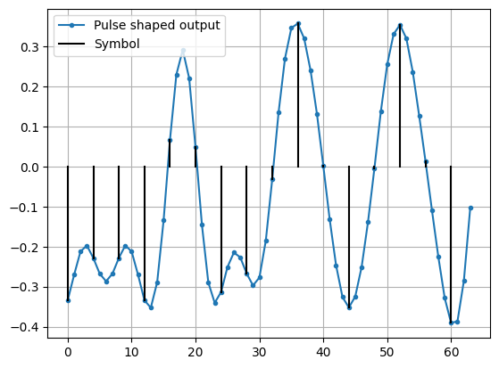
# Show time domain aspects of interpolation & pulse-shapinp
fig, ax = plt.subplots()
ax.plot(np.real(qpsk_tx_filtered[:num_disp_sym * L]), '.-', label='Pulse shaped output')
num_taps = 64
for i in range(num_disp_sym):
    if not i:
        plt.plot([i*L,i*L], [0, np.real(qpsk_tx_filtered[i*L])], color='k', label='Symbol')
    else:
        plt.plot([i*L,i*L], [0, np.real(qpsk_tx_filtered[i*L])], color='k')
plt.grid(True)
plt.legend()
plt.show()
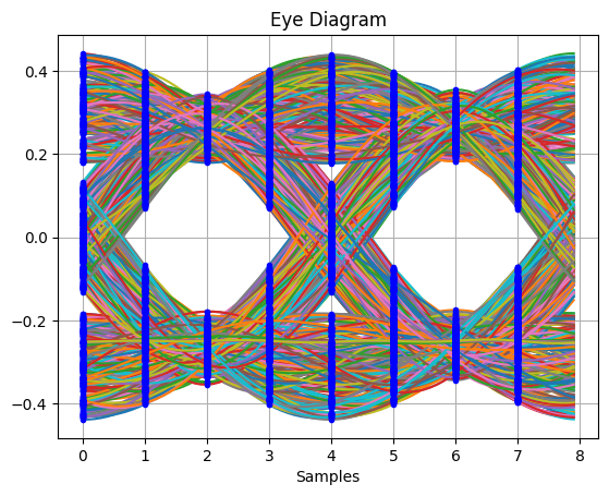
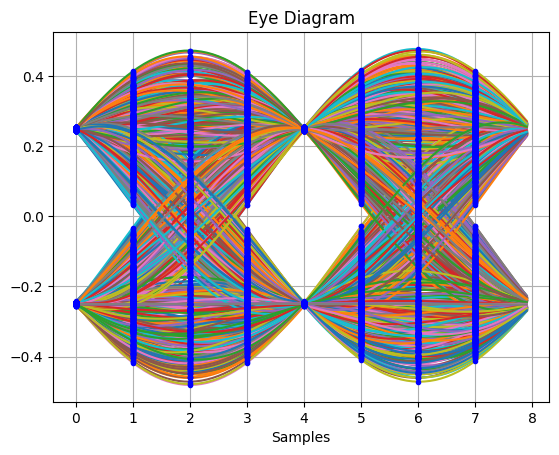
_,_ = plot.eye(qpsk_tx_filtered.real, L)
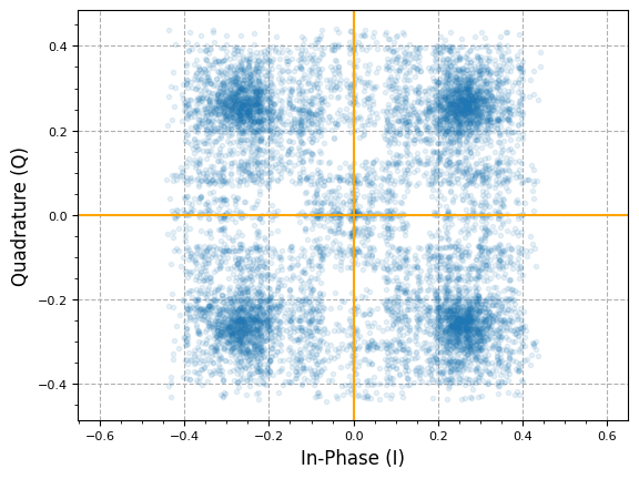
plot.IQ(qpsk_tx_filtered, alpha=0.1)
plt.show()
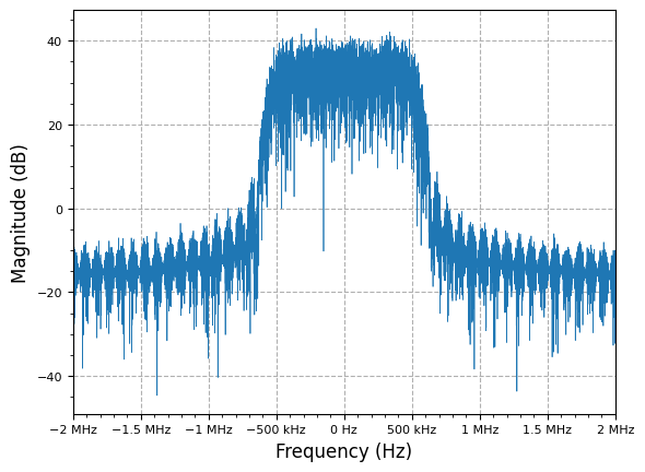
plot.spec_an(qpsk_tx_filtered, fs=fs, fft_shift=True, show_SFDR=False, y_unit="dB")
plt.show()
# Pass transmitted waveform through same RRC (matched filter)
rrc_coef = filter.RootRaisedCosine(L * sym_rate, sym_rate, rolloff, 2 * num_filt_symbols * L + 1)
rx_shaped = signal.lfilter(rrc_coef, 1, qpsk_tx_filtered)
# don't plot begining samples while starting filter convolution process
transient = (len(rrc_coef)//2 + 1) * L
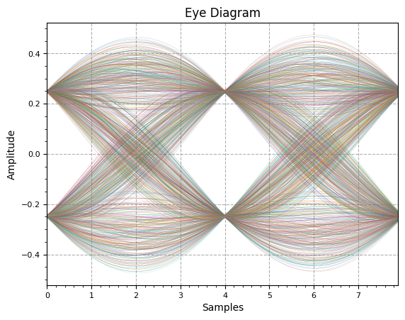
_,_ = plot.eye(rx_shaped.real[transient:], L )

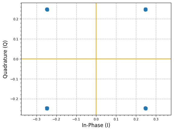
# adjust for best EVM, similar to slicer
timing_offset = 4
plot.IQ(rx_shaped[transient + timing_offset::4], alpha=0.1)
plt.show()
Derivative Matched Filter (DMF)
A derivative matched filter (DMF) is simply the time derivative of the receive matched filter (MF). If the MF impulse response is (here a root-raised-cosine, RRC), then
Because it responds to the slope of the pulse instead of its peak, the DMF is the core of maximum-likelihood timing error detectors (TEDs). At the correct sampling instant the MF output sits at its peak, where the derivative is zero, so the DMF output crosses through zero and yields a signed timing error. In practice the received signal is passed through both filters and the error is formed from the product of their outputs, . This is exactly the structure of Harris-style polyphase filterbank (PFB) timing recovery: one polyphase bank implements the interpolating MF and a parallel bank implements the DMF, and the ratio of the two bank outputs drives the loop accumulator that selects the correct polyphase arm (fractional delay). The same MF/DMF pairing shows up in MMSE/gradient early-late TEDs and band-edge timing loops.
There are two common ways to build the DMF taps from the MF taps:
1. Frequency-domain (spectral) derivative. Differentiation in time is multiplication by in frequency:
We take the DFT of the MF taps, multiply by the ideal differentiator ramp , and inverse-transform. This is exact on the DFT grid and full-band, but the ramp amplifies out-of-band noise and finite-length (Gibbs) ripple.
2. Numerical derivative via central differences. Approximate the derivative directly from the taps using the central difference, i.e. the average of the forward and backward differences:
which is convolution with the 3-tap kernel (with a one-sided forward/backward difference at the two end taps). This is what numpy.gradient computes. Its frequency response is
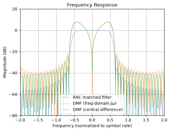
so it matches the ideal differentiator near DC but rolls off as toward Nyquist. Since the RRC pulse is oversampled () and its energy lies well below Nyquist (band edge near , where ), the cheap central-difference DMF is nearly identical to the spectral DMF across the signal band while staying better-behaved out of band.
Which to use for a Harris PFB TED? This is really a coefficient-design choice, not an architectural one: at run time the matched-filter bank and its derivative bank are both evaluated every symbol, so the derivative filter costs the same to run no matter how its taps were generated. The central-difference method is the easy default — the derivative taps fall straight out of the matched-filter taps (subtract neighbors; no separate differentiator to design), it adds no out-of-band noise gain, and because the prototype is oversampled by its polyphase arms the signal band sits far below Nyquist where is essentially exact. Reach for the frequency-domain method when you need an accurate full-band derivative, or when the filter is only lightly oversampled (few samples-per-symbol) and the rolloff would distort the timing S-curve near the band edge.
Software vs. hardware implementation. The finite-difference view says the derivative arm is just the difference of adjacent matched-filter arms, . In a software loop you can apply that straight at the output when the neighboring arm outputs are already on hand, , avoiding a dedicated derivative filter altogether. On an FPGA/ASIC the natural structure is the opposite: instantiate a second, parallel derivative PFB with its own precomputed coefficient memory, driven by the same arm-select index as the matched-filter bank. That is the cleanest, highest-throughput layout, and since the derivative taps are just stored constants, the central-difference-vs- decision carries no hardware cost, it only changes the values programmed into the coefficient ROM. In other words, the “no second prototype” savings is a software convenience; in hardware you almost always pay for the second bank (which is cheap and identical in size to the MF bank) and simply bake the chosen derivative taps into it.
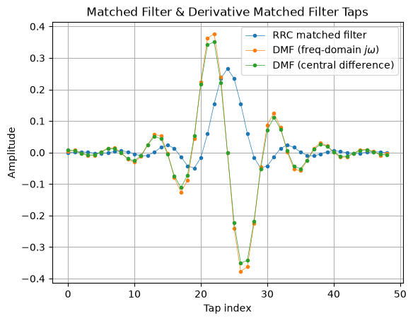
The plots below overlay the RRC matched filter with both DMF constructions (the difference-based taps are scaled by so the low-frequency slopes align).
n_fft = 2048
freq_bins = np.linspace(-L / 2, L / 2, n_fft)

# Method 1: frequency-domain (spectral) derivative: multiply MF spectrum by j*w
H_rrc = np.fft.fft(rrc_coef, n_fft)
H_dmf = 1j * 2 * np.pi * np.fft.fftfreq(n_fft) * L * H_rrc
dmf_fd = np.real(np.fft.ifft(H_dmf)[: len(rrc_coef)])

# Method 2: numerical derivative via central (forward/backward) differences
# central difference = (h[n+1] - h[n-1]) / 2, i.e. convolution with [1, 0, -1]/2;
# np.gradient uses one-sided forward/backward differences at the two end taps.
# Scale by L to match the j*w*L slope used in the spectral method above.
dmf_cd = L * np.gradient(rrc_coef)

print(f"Num taps: len(RRC)={len(rrc_coef)}, len(DMF Freq)={len(dmf_fd)}, len(DMF CD)={len(dmf_cd)}")

# Frequency responses (dB)
Y_rrc = 20.0 * np.log10(np.abs(np.fft.fftshift(H_rrc)))
Y_fd = 20.0 * np.log10(np.abs(np.fft.fftshift(np.fft.fft(dmf_fd, n_fft))))
Y_cd = 20.0 * np.log10(np.abs(np.fft.fftshift(np.fft.fft(dmf_cd, n_fft))))

# Time-domain filter taps
plt.figure()
plt.plot(rrc_coef, '.-', linewidth=0.5, label='RRC matched filter')
plt.plot(dmf_fd, '.-', linewidth=0.5, label=r'DMF (freq-domain $j\omega$)')
plt.plot(dmf_cd, '.-', linewidth=0.5, label='DMF (central difference)')
plt.title('Matched Filter & Derivative Matched Filter Taps')
plt.xlabel('Tap index')
plt.ylabel('Amplitude')
plt.grid(True)
plt.legend()
plt.show()

# Frequency responses
plt.figure()
plt.plot(freq_bins, Y_rrc, linewidth=0.5, label='RRC matched filter')
plt.plot(freq_bins, Y_fd, linewidth=0.5, label=r'DMF (freq-domain $j\omega$)')
plt.plot(freq_bins, Y_cd, linewidth=0.5, label='DMF (central difference)')
plt.title('Frequency Response')
plt.xlabel('Frequency (normalized to symbol rate)')
plt.ylabel('Magnitude (dB)')
plt.ylim([-80, 20])
plt.margins(x=0)
plt.grid(True)
plt.legend()
plt.show()
Num taps: len(RRC)=49, len(DMF Freq)=49, len(DMF CD)=49
/tmp/ipykernel_2797/1085860097.py:20: RuntimeWarning: divide by zero encountered in log10 Y_cd = 20.0 * np.log10(np.abs(np.fft.fftshift(np.fft.fft(dmf_cd, n_fft))))
References
- Digital Pulse-Shaping Filter Basics - ADI AN-922
- Root Raised Cosine (RRC) Filters and Pulse Shaping in Communication Systems - NASA
- Frequency Response of RRC Filter - DSP Stack Exchange
- Raised Cosine Filtering - MATLAB
- Raised-Cosine Filter - Wikipedia
- The care and feeding of digital, pulse-shaping filters
- Matched Filter - Wikipedia
Maintained by John Gentile • Found a problem on this site? File an Issue
This work is licensed under a Creative Commons Attribution 4.0 International License.