Antenna Arrays
Est. read time: 2 minutes | Last updated: March 31, 2025 by John Gentile
Contents
from IPython.display import YouTubeVideo
Uniform Linear Array (ULA)

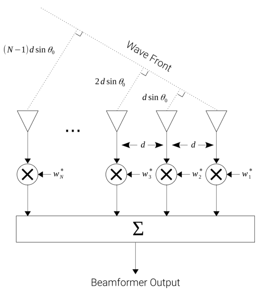
A ULA is defined as an array with elements equally spaced a distance from each other along a linear axis. Each RF channel- related to an RF antenna element- is sampled synchronously such that the digital samples are aligned in time across all channels so coherent processing can be performed. It can be seen that when dealing with a signal from the far field impinging on the array with angle, , the difference in propagation path length, , between elements in a ULA is given by:
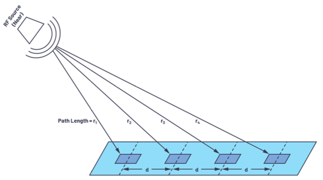
The reason we assume far field characteristics for the majority of this work to simplify the math and operations of phased arrays; for the case of a phased array receiver in the near field, an RF emitter is so close to the array that the incident angle of the received energy is different for every element due to the spherical wavefront of the source:

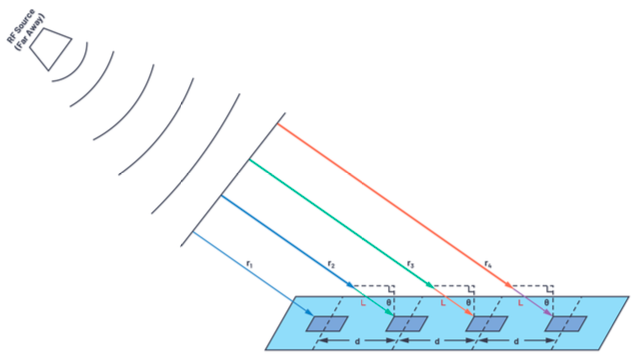
However, in the far field, where the same emitter is farther away from the receiving array, the wavefronts become approximately planar, and each receive element sees an equivalent incidence angle, , of the arriving wave:

The specific point at which a given system is operating in the far field is dependent on many factors of the array’s antenna properties, however a general equation can be found based on an array’s antenna diameter, , and the wavelength of the operating carrier frequency, :
References
- petotamas/pyArgus: Antenna array signal processing library implemented in python
- zinka/arraytool: Python based package for phased array antenna design and analysis
-
[Phased Array Antenna Patterns—Part 1: Linear Array Beam Characteristics and Array Factor Analog Devices](https://www.analog.com/en/analog-dialogue/articles/phased-array-antenna-patterns-part1.html#) -
[Phased Array Antenna Patterns—Part 2: Grating Lobes and Beam Squint Analog Devices](https://www.analog.com/en/analog-dialogue/articles/phased-array-antenna-patterns-part2.html) -
[Phased Array Antenna Patterns—Part 3: Sidelobes and Tapering Analog Devices](https://www.analog.com/en/analog-dialogue/articles/phased-array-antenna-patterns-part3.html) -
[RF Transceivers Enable Forced Spurious Decorrelation in Digital Beamforming Phased Arrays Analog Devices](https://www.analog.com/en/technical-articles/rf-transceivers-enable-forced-spurious-decorrelation-in-digital-beamforming-phased-arrays.html) - Phased Arrays - Steering and the Antenna Pattern Notebook
YouTubeVideo('jSDLfcNhThw')